Rasterization
Rasterization is the process of converting vector graphics into dot matrix graphics. Nearly all modern real-time graphics are rasterized:
- OpenGL
- DirectX
- Vulkan
The simplest form of this is triangle rasterization. Essentially, given a triangle in coordinates, you want to find that which pixels on the screen overlap with the triangle’s area. We treat each pixel as a single point in space(rather than a small area, which is what it really is).
The naive approach to solving this problem is to iterate through each pixel in the image and test whether or not it falls within the bounds of each triangle. However, this method unnecessarily looks at every pixel and tests each pixel against each triangle. The best approach is to reverse it, and iterate through each triangle and figure out which pixels form it.
Imagine treating the image as a set of rows. You can find where each row enters and exits each triangle. However, even this is still too inefficient. We want to only test the rows that are guaranteed to overlap with the triangle. Another optimization we can do is to create bounding boxes. If we create a bounding box around any shape, we can get the rows that are guaranteed to intersect it, which will speed up intersection testing.
Now we have a method for rasterization. However, this relies on a very import equation:
Line Segment Intersection
If we have four endpoints of our lines $(p_1, p_2), (q_1, q_2)$, and we wanted to find where and if they intersect, we can first get their slope: $$ m = (q_2.y - q_1.y)/(q_2.x-q_1.x) $$ Given the slope, we can get them in point slope form: $$ Y = m(X-q_1.x) + q_1.y $$ Once we have both lines as point-slope equations, we can use them to solve for $X$. We know that $X$ and $Y$ must be equal where the lines intersect. We can structure the equation like this: $$ m_1X - m_1p_1.x + p_1.y = m_2X - m_2q_1.x + q_1.y $$ For a row, we know that $m_1$ is 0. Furthermore, $Y$ is already known(since we are iterating on the rows). We get the following equation that we can solve for $X$: $$ p_1.y = m_2X - m_2q_1.x + q_1.y $$ However, this doesn’t work for all triangles. There are multiple edge cases:
Out of Range: The lines that we create and check intersections for are infinite. We have put no bounds on the lines of the triangle. Therefore, we need to make sure that the pixel row only tests for intersection with edges within the bounding box. We essentially need to check that the pixel’s y coordinate is within the y coordinates of the bounding box
Zero Slope Edge: If the slope of the edge of a triangle is zero and the edge is colinear to the pixel row being tested, then we have an ambiguous situation of having an “infinite” number of intersections. However, this edge case has a nice solution: just ignore the edge. This is because the other edges will intersect the lines for it and create a pseudo edge, so we really don’t need to worry about the flat edge.
Undefined Slope Edge: If the slope of the triangle edge is undefined(perfectly vertical), then we have no way to calculate its slope or use it in an equation to get an intersection. However, in this case, we can just use the X coordinate of either point.
Culling Geometry Optimization
We don’t want to waste time trying to render triangles that are outside our viewport. Therefore, we can ignore any triangles outside our viewport and clamp the bounding boxes of the remaining triangles to the viewport.
Overlapping Triangles
In most images, you will have multiple triangles overlapping the same image. We then ask, which triangles color should we use for a pixel that has two triangles? The solution for this is the Painter’s Algorithm. All this means is that we sort the shapes by their “z-distance” from the screen, with the farthest first. Then, we draw the shapes in order, painting over previously drawn shapes as we iterate through the list.
We still have an issue. What if we have intersecting shapes that create a cyclical overlap?
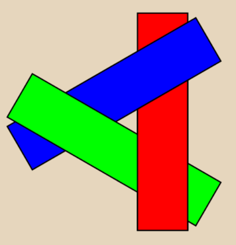
This tells us that we need to sort on a per-pixel basis rather than on a per-triangle basis.
Z-Buffering
When we identify pixels that overlap a triangle, we store the z-coordinate of the portion of the triangle that is overlapped. The z-coordinate is stored as inside the pixel as a part of a data bundle known as a “fragment”.
Fragments
Fragments are data bundles stored with each pixel. They store things like(but not limited to):
- Z-coordinate
- Color
- Texture coordinate
- Transparency/Alpha
Fragments are better described as “potential pixels”. How a pixel’s color is chosen is dependent on the renderers method of depth sorting and alpha blending. A given pixel will have $n$ fragments associated with it, where $n$ is the number of triangles that overlap it.
Going back to Z-buffering, now that we have the set of fragments for each pixel, we can determine its color. The easiest solution would just be to use the frag with the smallest z-coordinate. A more advanced solution would be to sort fragments based on depth and combine colors based on transparency.
We also want to make sure that we use large enough floating point numbers in Z-buffering to prevent Z-fighting, which is when two shapes are close enough that floating-point errors cause both shapes to flicker in and out of visibility.
Interpolation within a Triangle
To interpolate within a triangle we use barycentric coordinates. Given a point $P$ on a triangle $P_1, P_2, P_3$, we weight the value at each vertex based on the area $P$ makes with the opposite two points.
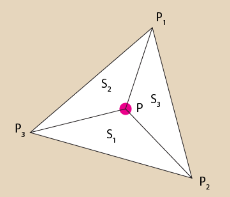
We know the area of a triangle can be computed by cross product: $$ A = 0.5\cdot length(cross(P_1-P_2, P_3-P_2)) $$ The cross product will span the parallelogram created by those two vectors. By diving it in half, you get the area of the triangle.
To get interpolated fragment attributes, such as color, we use the following method of barycentric coordinates: $$ P.color = P_1.color \cdot \frac{Area(S_1)}{Area(S)} + P_2.color \cdot \frac{Area(S_2)}{Area(S)} + P_3.color \cdot\frac{Area(S_3)}{Area(S)} $$
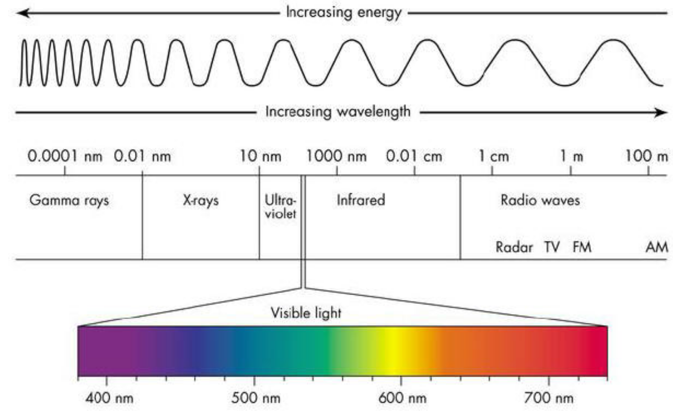
Color
Remember that color is electromagnetic radiation with wavelengths between 390 and 700 nanometers. This spectrum is visible to the human eye.
There also exists a standard called the CIE Chromaticity Diagram. This represents the gamut of colors visible to humans.
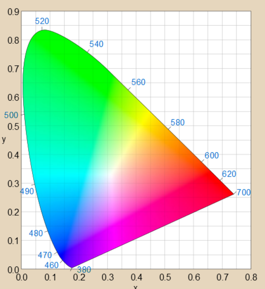
Colors along the outside border are pure wavelengths. Colors on the inside are combinations of wavelengths. Colors along the “line of purple” at the bottom are combinations of pure violet and pure red.
Modern display hardware uses combinations of pure red, pure green, and pure blue light to generate colors. Computers can only really generate a subset of the gamut of visible light. Most modern hardware uses 32 bits to represent an RGBA channel, with 8 bits for each.
Light Approximation via RGB
RGB values are each in the range [0, 1]. White is (1, 1, 1) and black is (0, 0, 0). However, visual perception of a surface’s color is a component-wise product. Emitted light color is denoted $(R_L, G_L, B_L)$, and the surface’s intrinsic color is denoted $(R_S, G_S, B_S)$. To get the surface’s reflected or perceived color, we simply do component-wise multiplication: $(R_L\cdot R_S, G_L \cdot G_S, B_L\cdot B_S)$.
Here are some examples:
- White light on a red surface = Red
- $(1, 1, 1) \cdot (1, 0, 0) = (1, 0, 0)$
- Red light on a white surface = Red
- $(1, 0, 0) \cdot (1, 1, 1) = (1, 0, 0)$
- Red light on a green surface = Black
- $(1, 0, 0) \cdot (0, 1, 0) = (0, 0, 0)$
- Red light on a yellow surface = Red
- $(1, 0, 0) \cdot (1, 1, 0) = (1, 0, 0)$
Pigment Colors
By combining two primary light colors of $(R, G, B)$, you can get the primary colors of pigment: Cyan, Magenta, Yellow. Light is additive, while pigment is subtractive.
- Cyan + Yellow = Green
- $(0, 1, 1) \cdot (1, 1, 0) = (0, 1, 0)$
- Magenta + Yellow = Red
- $(1, 0, 1) \cdot (1, 1, 0) = (1, 0, 0)$
Polygon Meshes
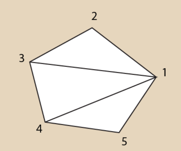
Polygons are often represented as a simple list of vertices. Vertices are often ordered in a CCW fashion. A question often asked is how to triangle rasterize an n-gon. The solution, of course, is to split it into multiple triangles. The general method for this is called the fan method, which will take a single vertex and will create a triangle with every remaining pair of vertices.
This method has generally remained unchanged for polygons. However, it only works on convex polygons. Concave polygons still lack a perfect way to triangulate them. The best known way right now is the ear-cut method.